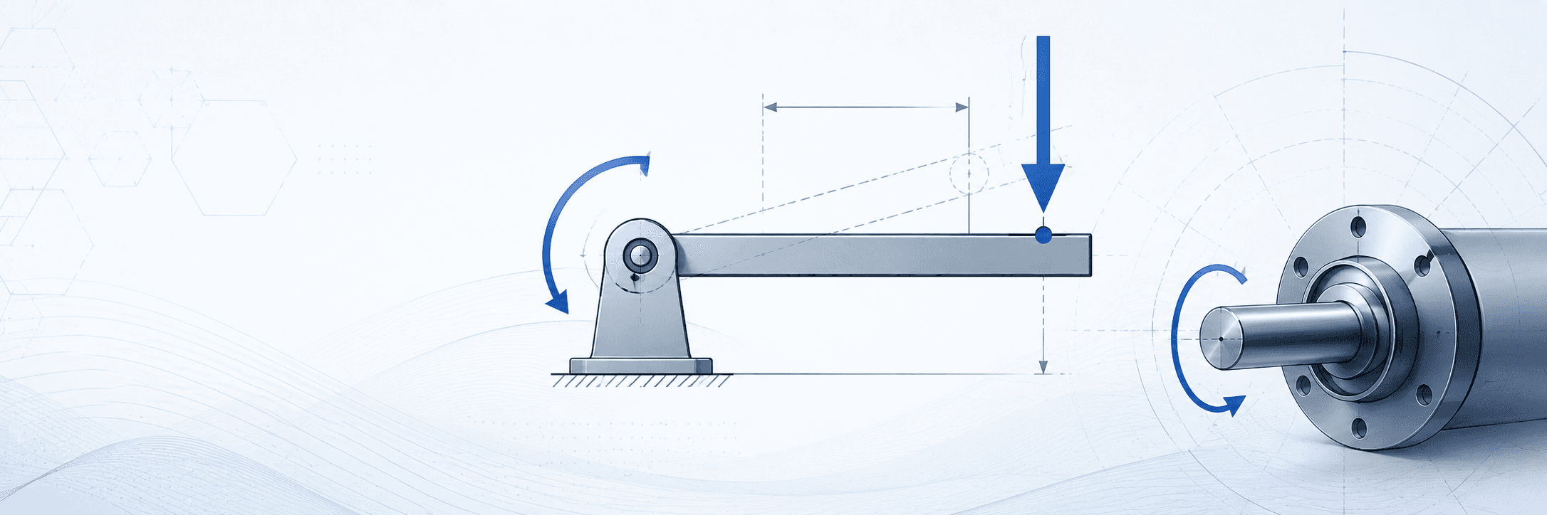
Force and Moment
Force and Moment
Understanding How Loads Act on Machines
Force and moment are among the most fundamental quantities in mechanical engineering.
A motor rotates a shaft.
A pneumatic cylinder pushes a product.
A blade cuts material.
A bearing supports a rotating shaft.
A frame carries the loads generated by the entire machine.
Although these phenomena appear different, they can all be interpreted through the same fundamental question:
How are forces and moments generated, transmitted, resisted, and transformed within a mechanical system?
Mechanical analysis therefore does not end with determining how many newtons of force act on a component.
A complete analysis asks:
Where does the force originate? In which direction does it act? Where is it applied? What moment does it create? Through which components is it transmitted? And what stresses and deformations does it finally produce?
This sequence forms the foundation of mechanical load analysis.
1. What Is Force?
Force is a vector quantity that can change the motion of a body or cause it to deform.
Newton's second law expresses the basic relationship:
F = ma
where:
F = Force [N]
m = Mass [kg]
a = Acceleration [m/s²]
Therefore:
1 N = 1 kg·m/s²
However, in mechanical design, knowing only the magnitude of a force is not sufficient.
For example:
F = 500 N
does not completely describe how that force affects a machine.
A force must be defined by at least four characteristics:
Magnitude
Direction
Point of application
Line of action
A 500 N horizontal force and a 500 N vertical force can produce completely different structural effects.
Likewise, even if the magnitude and direction are identical, moving the line of action away from a support or rotation center can create a significant moment.
This is where force and moment become inseparably connected.
2. Force as a Vector
Because force has both magnitude and direction, it must be treated as a vector.
In three-dimensional space:
F = Fx i + Fy j + Fz k
or:
F = (Fx, Fy, Fz)
For example:
Fx = 300 N
Fy = 400 N
Fz = 0 N
The magnitude of the resultant force is:
|F| = √(300² + 400²) = 500 N
Real machine loads rarely act in only one direction.
A helical gear, for example, can simultaneously generate:
Tangential force
Radial force
Axial force
The shaft, bearings, and housing must therefore be analyzed using the individual force components rather than only the total magnitude.
Vector decomposition is consequently one of the basic tools of mechanical load analysis.
3. Resultant Force
When several forces act on the same body, they may be combined into a resultant force.
The vector form is:
R = ΣFi
In three dimensions:
Rx = ΣFx
Ry = ΣFy
Rz = ΣFz
and the magnitude is:
|R| = √(Rx² + Ry² + Rz²)
However, simply adding all forces is not enough to describe the complete mechanical effect.
If those forces act at different positions, they also generate moments.
Therefore, a mechanical load system must generally be represented by both:
Resultant Force + Resultant Moment
4. What Is a Moment?
A moment describes the rotational effect produced by a force about a point or an axis.
In vector form:
M = r × F
where:
M = Moment [N·m]
r = Position vector from the reference point to the point of force application
F = Applied force
The magnitude is:
M = rF sin θ
or, more simply:
M = Fd
where d is the perpendicular distance between the reference point and the line of action of the force.
This perpendicular distance is often called the moment arm or lever arm.
Consider a 500 N force.
If the perpendicular distance is:
d = 0.1 m
then:
M = 500 × 0.1 = 50 N·m
If the same force acts at:
d = 0.5 m
then:
M = 500 × 0.5 = 250 N·m
The force has not changed, but its rotational effect has increased by a factor of five.
This demonstrates an important principle of mechanical design:
Load magnitude alone does not determine structural behavior. Geometry and load position are equally important.
5. Force and Moment in Translational and Rotational Motion
Force and moment have corresponding roles in linear and rotational motion.
For translational motion:
F = ma
For rotational motion:
M = Jα
where:
J = Mass moment of inertia [kg·m²]
α = Angular acceleration [rad/s²]
The correspondence is therefore:
Force → Translational Motion
Moment → Rotational Motion
Similarly:
Mass m → Resistance to linear acceleration
Mass moment of inertia J → Resistance to angular acceleration
This distinction becomes particularly important in high-speed machinery, servo systems, rotating blades, and robotic mechanisms.
6. Moment and Torque
Moment and torque use the same unit:
N·m
and mathematically both represent a rotational effect.
In mechanical engineering practice, however, the terms are often used somewhat differently.
Moment generally refers to the rotational or bending effect produced by a force.
Typical examples include:
Bending moment
Frame moment
Support moment
Torque is commonly used when rotational power is transmitted through a shaft or rotating element.
Examples include:
Motor torque
Gearbox output torque
Shaft torque
A useful practical interpretation is:
Moment = General rotational effect of a force
Torque = Moment associated primarily with rotational power transmission
7. Couple Moment
A special type of load system is a couple.
A couple consists of two forces that:
Have equal magnitude
Act in opposite directions
Have parallel lines of action
Are separated by a distance
The net force is:
ΣF = 0
but a moment remains:
M = Fd
This is called a couple moment.
A particularly important property of a couple is that its moment is independent of the reference point.
It creates pure rotational action without a net translational force.
Torque transmitted through a rotating shaft can often be interpreted as a couple.
8. Equivalent Force-Couple System
A force cannot generally be moved from one location to another without changing its mechanical effect.
Suppose a force F acts at point A.
If we want to represent the same loading at another point O, we must introduce both:
The same force F
and an additional moment:
Mo = rOA × F
Therefore:
Force at A
is mechanically equivalent to:
Force at O + Moment about O
This is called a force-couple equivalent system.
The concept is extremely useful when simplifying complex machine loads or reducing several loads to a common reference point.
9. Concentrated and Distributed Loads
Not all loads act at a single point.
Concentrated Load
A concentrated load is idealized as acting at one point.
Typical examples include:
Bearing reactions
Pin forces
Bolt forces
Roller contact forces
Distributed Load
A distributed load acts over a length, surface, or volume.
For a line load described by:
w(x) [N/m]
the equivalent resultant force is:
R = ∫w(x) dx
Its position is determined by:
x̄ = ∫xw(x) dx / ∫w(x) dx
Therefore, even a complex distributed load can often be reduced to an equivalent resultant force acting at an appropriate location.
This reduction is fundamental in beam and structural analysis.
10. Equilibrium of Forces and Moments
For a body to remain in static equilibrium, both the total force and total moment must be zero.
For a two-dimensional system:
ΣFx = 0
ΣFy = 0
ΣM = 0
For a three-dimensional system:
ΣFx = 0
ΣFy = 0
ΣFz = 0
and:
ΣMx = 0
ΣMy = 0
ΣMz = 0
These equations form the basis for calculating:
Bearing reactions
Support reactions
Pin forces
Frame loads
Bolt loads
Structural reactions
Force equilibrium alone is not sufficient.
A body may have zero resultant force and still experience a nonzero moment.
Therefore, both force and moment equilibrium must always be considered.
11. Free-Body Diagrams
One of the most important tools in mechanical analysis is the Free-Body Diagram, or FBD.
Instead of analyzing an entire machine at once, a component or subsystem is isolated from its surroundings.
The physical connections to surrounding components are replaced by forces and moments.
For example, when a shaft is isolated, its FBD may contain:
Gear forces
Belt tension
Bearing reactions
Shaft weight
Applied torque
The actual surrounding components disappear from the diagram.
What remains is essentially:
Geometry + Forces + Moments + Constraints
This simplification makes it possible to calculate reactions and internal loads systematically.
A reliable mechanical calculation almost always begins with a correctly defined system boundary and a correct free-body diagram.
12. Common Sources of Force in Machines
Mechanical systems experience many different types of forces.
Weight
The gravitational force acting on a mass is:
W = mg
For a 50 kg component:
W = 50 × 9.81 ≈ 491 N
Inertial Force
When a mass accelerates:
F = ma
In high-speed mechanisms, inertial loads may become much larger than static weight.
Centripetal Force
For circular motion:
F = mv² / r
or:
F = mω²r
This becomes important in rotating mechanisms, blades, wheels, and high-speed machinery.
Friction Force
A simplified Coulomb friction model is:
Ff = μN
where μ is the coefficient of friction and N is the normal force.
Spring Force
For an ideal linear spring:
F = kx
Pneumatic and Hydraulic Force
The ideal actuator force is:
F = PA
where:
P = Pressure
A = Effective piston area
Actual actuator force is lower because of friction, back pressure, pressure losses, and other system effects.
13. External Loads Become Internal Loads
External forces and moments are transmitted through a component and appear internally as several basic load types.
The four most common are:
N — Axial Force
Produces tension or compression.
V — Shear Force
Attempts to slide one section of material relative to another.
M — Bending Moment
Causes a member to bend.
T — Torsional Moment
Causes a member to twist.
The mechanical sequence can therefore be expressed as:
External Load
→ Internal Load
→ Stress
→ Strain
→ Deformation
This relationship connects statics and dynamics to strength of materials and structural design.
14. From Force to Stress
Force and stress are not the same physical quantity.
For a simple axial load:
σ = N / A
where:
σ = Normal stress
N = Axial force
A = Cross-sectional area
A force describes the load acting on a body.
Stress describes how that load is distributed inside the material.
The units are also different:
Force:
N
Stress:
Pa = N/m²
The same 1,000 N load can produce very different stresses depending on the cross-sectional area carrying that load.
Therefore, structural safety cannot be determined from force alone.
15. From Bending Moment to Bending Stress
When a beam or structural member is subjected to a bending moment, bending stress develops across the cross-section.
For classical elastic bending:
σ = My / I
where:
M = Bending moment
y = Distance from the neutral axis
I = Second moment of area
This equation reveals one of the most important relationships in mechanical design.
Structural performance depends not only on material strength but also strongly on geometry.
Increasing the second moment of area can reduce bending stress and deformation without changing the material.
Therefore:
Load + Geometry + Material
must be considered together.
16. From Torque to Torsional Stress
When torque is applied to a circular shaft, torsional shear stress develops.
For a circular shaft:
τ = Tr / J
where:
T = Torque
r = Radial position
J = Polar second moment of area
For a solid circular shaft:
J = πd⁴ / 32
The fourth-power relationship with diameter is particularly important.
A relatively small change in shaft diameter can produce a large change in torsional stiffness and stress distribution.
This demonstrates why changing geometry can sometimes be a much more effective design measure than simply selecting a stronger material.
17. Converting Torque into Force
Many machines convert rotational torque into linear or tangential force.
For a pulley, sprocket, wheel, or gear with effective radius r:
F = T / r
For example:
T = 250 N·m
r = 0.1 m
then:
F = 250 / 0.1 = 2,500 N
The energy transmission path may therefore be represented as:
Motor
→ Shaft Torque
→ Gear / Pulley / Sprocket
→ Tangential Force
→ Mechanical Motion
This relationship connects rotational drive systems directly to the forces acting on machine components.
18. Power, Speed, and Torque
Rotational mechanical power is:
P = Tω
where:
P = Power [W]
T = Torque [N·m]
ω = Angular velocity [rad/s]
When motor power is expressed in kilowatts and rotational speed in rpm:
T [N·m] = 9550 × P [kW] / n [rpm]
This equation demonstrates why reducing rotational speed increases available torque for the same power.
A gearbox should therefore not be viewed simply as a device that reduces speed.
More fundamentally, it transforms the relationship between:
Speed ↔ Torque
For an ideal reducer:
Tout ≈ Tin × i
For a real reducer:
Tout = Tin × i × η
where:
i = Reduction ratio
η = Mechanical efficiency
19. Static and Dynamic Loads
A machine at rest and the same machine operating at high speed do not experience the same loads.
Consider a 20 kg moving component.
Its weight is approximately:
W = 20 × 9.81 ≈ 196 N
If the same component accelerates at:
a = 10 m/s²
the inertial load associated with that acceleration is:
F = 20 × 10 = 200 N
The acceleration load is already comparable to the component's own weight.
At higher accelerations, dynamic loads can easily dominate static loads.
This is particularly important in:
High-speed slicers
Servo feed mechanisms
Pick-and-place systems
Delta robots
Reciprocating mechanisms
In these systems, designing only for static weight can lead to serious underestimation of actual operating loads.
20. Rotational Inertia
For linear motion, resistance to acceleration is determined by mass:
F = ma
For rotational motion, it is determined by mass moment of inertia:
T = Jα
Two components can have the same total mass but very different rotational inertia.
Mass located farther away from the rotation axis produces a larger value of J.
This is especially important for:
Large pulleys
Rotating blades
Robot arms
Flywheels
High-speed rotating assemblies
Therefore, rotational systems cannot be analyzed using mass alone.
The spatial distribution of mass must also be considered.
21. Load Path
One of the most useful concepts in practical mechanical design is the load path.
A load does not simply act on one component and disappear.
Consider a cutting machine.
Power may be transmitted through:
Motor → Reducer → Shaft → Blade → Product
But the reaction force continues through the structure:
Product → Blade → Shaft → Bearing → Housing → Frame → Floor
The force therefore travels through a chain of mechanical interfaces.
At each interface:
Its direction may change
Its magnitude may change
A moment may be created
Stress concentration may occur
Deformation may develop
Understanding this path is often more important than calculating an isolated load on a single component.
22. Action and Reaction
Newton's third law states:
FAB = −FBA
When one component exerts a force on another, the second component exerts an equal and opposite force on the first.
If a cylinder pushes a product with 1,000 N, the cylinder mounting structure must also resist a 1,000 N reaction.
If a motor applies 200 N·m of torque to a shaft, the motor housing and its mounting structure experience an opposing reaction torque.
A common design error is to calculate the force acting on the driven component while neglecting the structure that must resist the reaction.
Every applied load therefore requires a corresponding load path through the supporting structure.
23. Three Different Meanings of “Moment”
The term moment appears in several important mechanical quantities that should not be confused.
Moment of a Force
M = r × F
Describes the rotational effect of a force.
Unit:
N·m
Mass Moment of Inertia
J = ∫r² dm
Describes resistance to angular acceleration.
Unit:
kg·m²
Second Moment of Area
I = ∫y² dA
Describes a cross-section's geometric resistance to bending.
Unit:
m⁴ or mm⁴
All three use the word “moment,” but they describe fundamentally different physical quantities.
24. A Basic Mechanical Load Analysis Process
A systematic load analysis can generally follow this sequence.
1. Define the System Boundary
Determine which component or subsystem will be analyzed.
2. Create a Free-Body Diagram
Remove surrounding components and replace their interactions with forces, moments, and constraints.
3. Define External Loads
Identify weight, actuator force, motor torque, cutting force, friction, inertia, and other loads.
4. Calculate Reactions
Determine forces and moments at bearings, supports, hinges, guides, and mounting points.
5. Determine Internal Loads
Calculate:
N, V, M, T
6. Calculate Stress
Evaluate tensile, compressive, shear, bending, and torsional stresses.
7. Calculate Deformation
Evaluate displacement, deflection, twist, and angular deformation.
8. Consider Dynamic Effects
Include acceleration, impact, vibration, and cyclic loading.
9. Evaluate Failure Modes
Check possible failure by:
Yielding
Fatigue
Buckling
Wear
Excessive deformation
Other relevant limit states
This basic logic applies from simple shafts and brackets to complete machine structures.
Understanding Force Means Understanding Relationships
A force in a machine is not merely a numerical value expressed in newtons.
A moment is not merely a numerical value expressed in newton-metres.
To understand how a machine behaves, the complete sequence must be considered:
Magnitude
→ Direction
→ Point of Application
→ Line of Action
→ Moment
→ Reaction
→ Load Path
→ Internal Load
→ Stress
→ Deformation
The important engineering question is therefore not only:
“How much force acts on this component?”
A more complete question is:
“Where does this force originate, in which direction does it act, through which components is it transmitted, what moments does it create, and where does it finally produce stress and deformation?”
Mechanical geometry and load transmission cannot be separated.
Geometry determines how forces flow through a machine, and the flow of forces determines what geometry the machine requires.
That relationship is one of the fundamental principles of mechanical design.